The Offical Sn2 Free-mo Standard
The Sn2 Free-mo standards are derived from the HO standard published at http://www.free-mo.org. The HO standards were tweaked to meet Sn2 specifics and the desires of the Sn2 modelers. The standard was developed with review of the sn2_trains yahoogroup.
Index
- 1.0 Introduction
- 2.0 Frame and Legs
- 3.0 Track
- 4.0 Wiring
- 5.0 Control
- 6.0 Scenery
- 7.0 Frequently Asked Questions
- 8.0 Glossary
- 9.0 Revision History
Legend
[Sx.y, RPx.y, FAQx.y, where x and y are numbers – example S2.15, RP5.11, FAQ1.7]
S = Standard. All Sn2 Free-mo modules and participants must conform to the requirement/standard stated.
RP = Recommended Practice. These are procedures or specifications which are strongly encouraged for maximum reliability and fidelity
FAQ = Frequently Asked Questions/Answers which explain the reasoning behind a particular Standard or recommended Practice.
1.0 Introduction
S1.1 The objective of the Sn2 Free-mo Standard is to provide a platform for prototype modeling in a flexible, modular environment. Free-mo modules provide track to operate realistic models, while emphasizing realistic, plausible scenery, realistic, reliable trackwork, and operations. Sn2 Free-mo is designed to push the envelope of modular model railroading to new heights. It goes beyond the traditional closed-loop setup in creating a truly universal “free-form” modular design that is operations oriented and heavily influenced by prototype railroading.
S1.2 Interoperability: The Sn2 Free-mo Standard is a collection of requirements for building scale model railroad modules that can work together with little effort, even when they have never been assembled together before. The beauty of the Sn2 Free-mo standard is that it allows builders to replicate any freelance or prototype trackplan within your modules boundaries, yet can be combined for maximal interoperability with other Free-mo modules.
S1.3 A Sn2 Free-mo module is a free-from module that confirms to the Sn2 Free-mo Standard as outlined below.
S1.4 The Sn2 Free-mo Standard governs the ends of the module and basic track requirements. Most Sn2 Free-mo modules have 2 ends, but modules can have one, two, three, or more ends.
S1.5 An Sn2 Free-mo module can be composed of more than one section. For modules composed of multiple sections, the Sn2 Free-mo standards apply to the endplates where the module will mate with other modules. The standard does not apply to the internal endplates of the module (end plates where the sections meet each other).
FAQ 1.5.1 The terms “module” and “section” are not interchangeable. A module consists of one or more sections. A section may or may not have a Sn2 Free-mo compatible endplate. The term “piece” is good to use when totaling the units in a Sn2 Free-mo setup (layout). For example a setup may consist of 15 modules totaling 24 pieces. This is possible if 10 modules on 1 peice and 3 modules are 2 sections and 2 modules are 4 sections.
2.0 Frame and Legs
S2.1 Endplates shall be 3/4″ plywood or equivalent (birch plywood works well) to provide sufficient strength for clamping to adjacent modules.
RP2.1.1 Avoid Dimensional Pine Lumber for your frame-work. It has a tendency to warp and “cup” with age, throwing of track alignment. It has also been found that plywood (birch plywood works well) warps and twists less than dimensional lumber (3/4″ inch pine boards).
S2.2 End plates shall be a minimum of 12″ wide and must be 6″ high. The end plate must be clear of obstructions in the clamping area that is a 2×4 inch space directly under the main line.

Sn2 Free-mo Endplate: 6″ high, 4″ minimum track from edge, but 6″ recomended for main.
RP2.2.1 Narrow modules are not as stable as wider modules, so wider modules are recommended for stability.
FAQ2.2.1 HO Free-mo standard requires 24″ wide end plates with exception of Mini-Mos.
FAQ2.2.2 The members of the Sn2 Crew have built modules of 12″, 16″, 18″, and 24″. The smaller sizes are more common.
FAQ2.2.3 Narrower modules are easier to transport.
RP2.2.2 Use “deep-throat” C-clamps to apply pressure closer to the top and draw track ends together.
S2.3 Double track modules are not supported by Sn2 Free-mo as no Maine 2-Foot gauge railroad had a double track module.
S2.4 Roadbed shall be 1/4″ high laid directly on top of the end plate and adequately supported throughout the rest of the module (to avoid sagging or flexing)
S2.5 The nominal and minimum height of the railhead, at the end plate, is 50 inches from the floor.
S2.6 There is no requirement for length of shape of a module.
RP2.6.1 Curved modules are highly recommended as they make a setup interesting and stable. The curvature of a module can be what the build wants as long as all track requirements (below) are in compliance.
RP2.6.2 A good supply of curved modules helps the coordinator design a the layout to fit any space.
FAQ: To date most curved modules are 45 or 90 degrees. More curves in the 10-30 degree range would be useful. The Fremo members in Europe often create many small degree curves. Such small modules are easy to transport and make it easy configure a layout to avoid obsticals (such as support pillars)
S2.6 HO free-mo supports grades on the mainline from end to end, but Sn2 Free-mo Standard does not yet support grades. The mainline through a module must be flat.
S2.7 Sn2 Free-mo does not support grades, so the maximum height is the same as the nominal minimum height of 50 inches above the floor.
S2.8 A module (set) shall have a least four legs and stand on its own.
FAQ2.8.1 The Sn2 Free-mo Standard does allow for Mini-mo modules, defined as a module 16″ or less wide, and less than 48″ long and less than 4 square feet. Several Mini-mo modules have been built 12″ wide and 24″ long.
S2.9 Legs shall have continuous adjustment of plus or minus 1 inch (screw type foot).
S2.10 The bottoms of the legs shall have rubber tip or equivalent floor protection.

Possible leg design and feet hardware
S2.11 Modules may be used with operators and spectators on either or both sides
FAQ2.11.1 Backdrops are not allowed or used during an Sn2 Free-mo setup. Members may have a backdrop at home (personal setup)
S2.12 Fascias must be smooth and made of a solid, sturdy material (plywood, hard board, Masonite, etc.). Fascia should be cut to meet the profile of the module terrain. Terrain should not be modified to meet a flat profile.
RP2.12.1 It is recommended that all controls be completely recessed in the fascia. Non-recessed controls tend to get broken during transport and operation. This goes for electrical plates, toggle switches, etc.
RP2.12.2 Color recommendations are to use natural colors associated with the scene. Earth (matching ballast) or light green to match ground foam colors. Black is not recommended, as it is too much of a contrast with the scene.
FAQ 2.12.1 The members of the Sn2 Crew are using the following fascia and earth scenery color. (2014 a new paint used on the modules at the 2014 Cleveland National NMRA train show) Print the images below and go to any Sherwin Williams store.
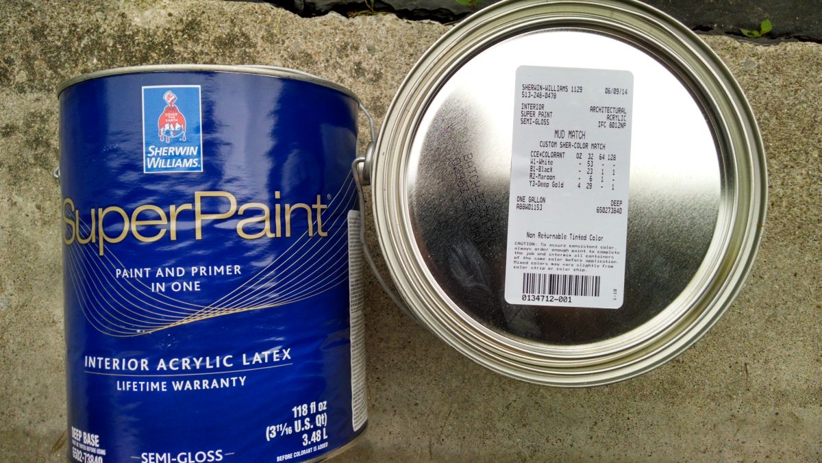
Sherwin Williams paint can
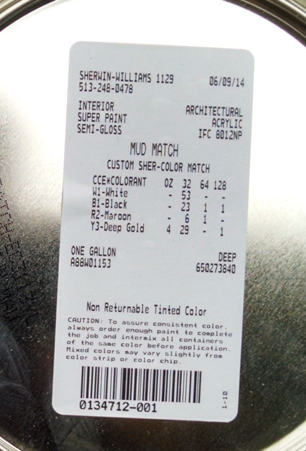
Formula shown on lid of the can
RP2.12.3 Use flat or satin colors for the fascia to minimize glare.
S2.13 There are no special benchwork construction requirements for modules in excess of what is specified above (S2.1-S2.11)
3.0 Track
S3.1 All HOn3 NMRA standards must be met (gauge, frog, flanges, guard rails). HO clearance standards must be met (the full profile of the gauge for clearances).
FAQ3.1.1 HOn3 track is 26.5″ gauge in S-scale. This standard is not attempting to do “Proto-64″ modeling on correct 3/8″ gauge rails. Participating in this standard is accepting this discrepancy.
S3.2 Sub-roadbed must be built to prevent sagging or flexing, and must be installed to comply with the end plate requirements in section 2.0. Track must be perpendicular to the end plate both horizontally and vertically!
3.3 Roadbed must comply with the 3/8” standard for top of scenery to rail-top dimension defined in section 2.0 above.
FAQ3.3.1 Many modules have been built using HOn3 homabed (http://www.homabed.com) for roadbed. It’s nominal height of .218″ (~7/32″) along with 5″ high ties (.078″ ~5/64″) and code 70 rail (0.78″) results in a height of rail being .366″ . Considering that some modules may use HOn3 flex track or code 55 rail, the rail height standard is being set as: Min 11/32″ Max: 3/8″ above end plate.
S3.1 Modules shall use hand-laid track or flex track
S3.2 The centerline of all tracks shall be 4 inches or more from the sides of the module at all locations.
RP3.2.1 It is recommended that mainline tracks be 6″ or more from the edge to ensure safety of moving trains.
S3.3 The track can be off-center at the end plate.
FAQ3.3.1 HO Free-mo requires track to be centered on the end plate. Sn2 Free-mo want to be inclusive, allowing the modeller to do what is best for his situation, so only recognizes S3.2 and RP3.2.1.
FAQ3.3.2 Members of the Sn2 crew have built mostly the following end plates: 12 inch wide track centered, 16 inch wide track centered, 18 inch wide off-set 6/12 inches from edge.
S3.4 Tracks internal to the module must be spaced a minimum of 1.75 inches a part.
S3.5 Tracks on the through route must be perpendicular to the end plate for 5 inches from each end plate.
S3.6 Tracks on the through route must be straight and level for 5 inches from each end of the module
RP3.6.1 The points of a turnout should not be within the 5″ of the end of a module.
S3.7 Rail shall be cut off 1 inch from module end; ties and ballast shall be continued to the module end for good appearance and matching with the adjacent module. Ties shall be notched under the ends of the rails and to the module end, to clear bridge rail joiners and provide freedom of adjustment for bridge rails.

RP3.7.1 Fitter rails must be Micro Engineering Code 70 and accommodate Micro Engineering code 70 joiners.
RP3.7.2 To enable DCC power districts, modules must be able to accommodate insulated rail joiners at each Free-mo endplate.
S3.8 Turnouts on the through route must be #8, when the through route takes the diverging portion of the turnout.
RP3.8.1 Because of the T&T big forney’s it is recomended that no turnout be smaller than a #7, even for spurs.
S3.9 There shall be a minum of 10 inches of straight track between reverse curves
S3.10 Track on the through route shall be code 70. The through route can be code 55, but then the module owner must provide transition fitter rails between code 55 and code 70.
RP3.10.1 Recomendation is to use weathered rail or to weather the rail. Same goes for fitter rails and all rail joiners.
S3.11 Siding, spurs and other tracks may be less than code 70, but must be compatible with NMRA HOn3 flange depth standards (Spike heads or other aspects of track must be implemented to ensure compliance)
S3.12 The minimum permitted curve radius on a through route is 32 inches. This includes sidings where through trains could be run.
RP3.12.1 While 32 inches is the minimum, it is highly recomended modules use 36 inches and/or easments. If using curves less than 36″ radius, easments are highly recomended.
RP3.12.2 Non-through routes can have sharper than 32″ radius curves, but it is not recommended.
S3.13 Spacing between tracks on curves of a module shall allow for long cars to operate without fouling each other. 2 inches is probably sufficient, but 2.25 inches would be better.
S3.14 Grades are not supported by Sn2 Free-mo through routes. On sidings it is recommended to keep the grades at 2″ or less. Forney’s are not good with grades.
S3.15 Vertical curves should be as long as possible.
4.0 Wiring
S4.1 Wiring consissts of 1 pair of bus wires (track bus)
S4.2 Track bus shall be 12-16 AWG stranded wire or better yet 12 AWG stranded wire.
S4.3 The Sn2 Free-mo standared does not include a DCC communication bus (Such as loconet or xpressnet or other). The Sn2 Free-mo Standard is independent of DCC system.
S4.5 All ends shall have a two anderson power poles for the track bus. One red and one black. The wire shall extend 6″ beyond the center of the end of the module. When facing the end of a module, the red connector is connected to the right rail (Red = Right). The black connector is connected to the left rail.

Track bus 30amp Powerpoles, notice alignement of “tonge” on connectors
FAQ4.5.1 The 30amp Anderson Powerpoles are available throuh the web. Once source is http://www.powerwerx.com Be sure to get 30amp, as other amperages are available, but not compatible.
FAQ4.5.2 Because the right rail is always red when facing the end of module, powerpoles are connected red to bleck, not red to red.
S4.6 Sn2 Free-mo does not have an accessor bus
S4.7 Sn2 Free-mo does not have a network bus
S4.8 Through route wiring is as follows:
S4.9 Track feeder wire must be 18-22 AWG or larger, but not longer than six inches to the track bus to avoid voltage loss.

General track bus wiring
S4.10 All turnout frogs shall be powered. Thurnouts shall not rely on switch points to power the frog.
FAQ4.10.1 This is often referred to as a DCC friendly turnout. The following web site has good information on gapping turnouts: http://www.wiringfordcc.com/switches.htm
S4.11 Modules must supply their own accessor power. Owners must not assume that all of their modules will be adjacent.
S4.12 Modules are not required to have DCC throttle panels
FAQ4.12.1 Several members of the Sn2 crew have Lenz DCC, so have installed Lenz and/or Atlas DCC panels in thier modules.
FAQ4.12.2 Cables are brought to the meets to connect the panels between modules. The cables often run under multiple modules.
RP4.12.1 To keep cables from lying on the ground, it is recommend that module provide a corss brace in the legs so that DCC network cables and power cords can be run.
S4.13 Each setup can choose it’s DCC system or DC. It is up to the participants of the setup to bring the proper cables.
S4.14 DCC….
S4.15 Multiple DCC boosters can be used. In
5.0 Control
S5.1 No proprietary DCC accessories may be used. Modules must be able to operate independent of DCC system and be able to work with DC.
FAQ5.1.1 Some modules built todate do have DCC accessories, so can not be run with DC. However, no DC setups have occured since 2006. So participants should expect that most setups will be DCC, so bring equipment that is DCC compliant.
S5.2 For a given turnout, turnout controls must be on all sides of module or module section, excepting any end plates. The intent is to be able to operate all modules from all sides.
FAQ5.2.1 Turnouts may be controled by ground throws, provided the frogs are power routed. As of January 2011, no modules have been built with ground throws. All are under track switch machines/motors or under track mechanical throws (such as blue points or bull frog).
FAQ5.2.2 Turnouts may be thrown by DCC accessory decode, but that must not be the only means. Some means at the side of the module must be provided.
S5.3 Turnout controls shall be located on the fascia, not on the horzontal or vertical surfaces of scenery.
6.0 Scenery
S6.1 All benchwork shall be hidden by some from of scenery.
S6.2 General module fascia color shall complement scenery and not draw attention from the scene.
RP6.2.1 To use an earth color very similar to Polyscale Earth (or is it mud).
FAQ6.2.1 All modules todate have been painted with an earth collor.
S6.3 Scenery at the Free-mo standard end(s) shall have a flat profile 3/8″ below the top of the rail of the through route (basically the scenery foam is directly on top of the endplate). Distictive or directional scenery features (such as road, fences, rivers, etc.) should not intersect the endplate.
RP6.3.1 During setups, apply additional scenery to cover the module joint. Polyfiber covered in foam, Woodland Scenic Clumps, Woodland Scenics follarge, Noch Grasses, etc. are all good choices to hid the module edges.
S6.4 The through route shall be ballasted
FAQ6.4 The general knowledge of Maine 2-Foot ballast is that it was local dirt or gravel (the exception that the Monson had slate ballast). The recomended ballast for Maine 2-foot modules is Smith and Son 8100 Fine Dirt; 8101 Medium Dirt; and/or 8102 Coarse Dirt (Smith and Son 13630 GAR HWY; Chardon, OH 44024; 440-286-4890 after 6pm EST)
S6.5 Rail should be weathered. Use weather ME rail, rail brown or roof brown paint.
7.0 Public Displays
RP7.0.1 Skirting is highly recommended and may be required by setup cordinator. Each end of skirt extends 2″ past the module endplate to ensure adequate coverage and no “gaps” at the module joints. Bottom edge of skirt is even with bottom of leg vertical members (i.e at the level of the T-nut) to prevent dragging on the floor regardless of the module height setting. Skirting is to be attached to bottom of module so that there are not gaps between skirting and module bottom. Either fold skirting to attach to bottom or tuck skirting into frame. Another option is to attach skirting to legs.
FAQ7.0.1 Sn2 module owners adopted a forest green color that was fire retardant (check Sn2 archives).
RP7.1.1 Modules should provide crowd control barrier system. Each module that is 5′ or longer must provide two barrier stands for every 5′ of length. Modules less than 5′ must supply a single barrier stand. Barrier stands consist of bases and uprights designed for simple construction and setup, and which may be separated for more efficient storage and transport. 1/4″ yellow nylon style rops (available at any hardware store) and threaded through the stands as a barrier.
FAQ7.1.1 Stand bases are 12″ square made from 1.5″ plywood (or equivalent multiple plywood layers). Painted white or yellow, is optional. A hole is centered in the base to accommodate a 1/2″ white PVC pipe end cap, firmly wedged into the hole and used to receive the stand upright. Stand uprights press-fit into the base and are 36″ tall 1/2″ white PVC pipe with a PVC “T-junction” mounted on top, through which the nylon rop is threaded. Paint is not allowed – leave uprights white.
FAQ7.1.2 Todate, barriers have not been used much (maybe only once), as most events have been for model railroaders, not general public. Thus the barrier is just a recommended practice, not a standard.
RP7.2.1 Plexiglas shields are allowed, but must be easy to remove for cleaning. The shields must not inhibit operations.
8.0 Glossary
- MODULE: Any layout component (or group of “sections”) meant to be operated as a single unit in a fixed configuration. A module can have any number of sections.
- SECTION: A part of a larger module, complete with benchwork, track, scenery, etc. Except where otherwise noted, standards for module interfaces donot apply to inter-section interfaces, as these are considered to be internal to the module.
- ENDPLATE: The standardized end surface of a module that joins with an adjacent module in a Free-mo layout. The physical aspects of the enplate are defined in the standard.
- FITTER RAILS: The 2″ long removable rails and joiners used to bridge the joints between adjacent modules or sections (Must be code 70).
- TRACK (POWER) BUS: The continuous two wire bus feeding power and DCC command to the track.
- EVENT: An organized gathering (show, meet, convention, etc…) that includes the display of model railroads.
- SETUP: A collection of free-mo modules connected together to form a layout. There may be more than one setup at an event.
- COORDINATOR: Person(s) responsible for organizing the participants, selecting themes, and securing space and utilities with event staff. Coordinator is likely a participant too.
- PARTICIPANT: A person who contributes to a setup by brining module(s), rolling stock or other components.
8.0 Revision History

I would be glad to proofread and correct misspellings, etc if you want that done.